DS903: The KPW (Kilogram Power Wheel)
A domestic power storage device replacing batteries
(With potential to upgrade to the KPT, Kilogram Power Torus)
David Noel
<davidn@aoi.com.au>
Ben Franklin Centre for Theoretical Research
PO Box 27, Subiaco, WA 6008, Australia.
What is a KPW?
The Kilogram Power Wheel is a device used to store energy at the domestic scale. Intended as part of an electricity-supply facility, it may be used instead of a bank of electrical batteries (sometimes called a "power-wall"). It is essentially a magnetically-levitated flywheel operating in a vacuum.
Electricity supply for households
Currently, many households depend for their electricity supply on power generated at a power station and sent to them through a network of wires (the "Grid"). Usually the power station makes power at a high voltage, and this is "stepped down" to lower voltages at one or more electrical "transformers" along the way.
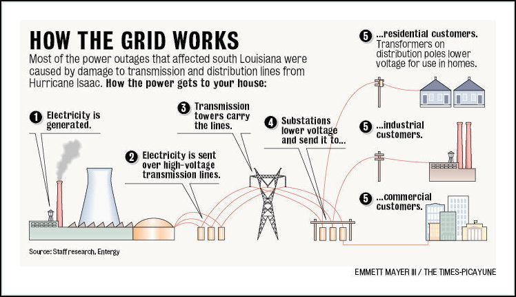
Fig. DS903-F1. The grid -- power station and distribution network. From [2].
Currently most commercial power stations produce and supply electricity as AC (Alternating Current), where the voltage varies as a sine wave each cycle. Most countries now supply AC at 50 cycles (per second), although the USA commonly uses 60 cycles.
In earlier times, some power stations produced DC (Direct Current) electricity, where the voltage (pressure) of the electricity was constant, and did not vary in cycles. DC and AC each have their advantages and disadvantages, depending on voltage changes needed and on transmission line lengths.
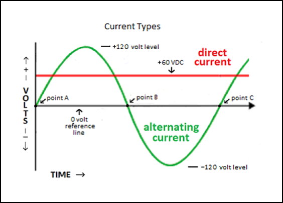
Fig. DS903-F2. AC and DC -- Alternating and Direct Current. From [3].
In recent years, many households have adopted solar panels on their roofs. These generate DC power from light falling on them, and so do not work at night. In a household situation, electricity from solar power cells needs conversion to AC (through an alternator) if it is to be used with typical 240 or 120 Volts AC wiring.
Because solar panels do not generate power at night or in other low-light conditions, households cannot rely on solar panels alone to supply their electricity needs. Therefore most households need to stay connected to the Grid, even though they could generate enough power for their total needs, because their solar power is not available at night.
The big majority of households with solar panels have agreements under which they sell all or some of their solar electricity to their power utility, and buy electricity from the utility when they need it.
Energy Storage for Households
Households could generate enough energy from solar panels to supply all their needs and go "off-grid", if they could store excess power during the day and call on the stored power during the night. At present, this means storing energy in a bank of electrical batteries.
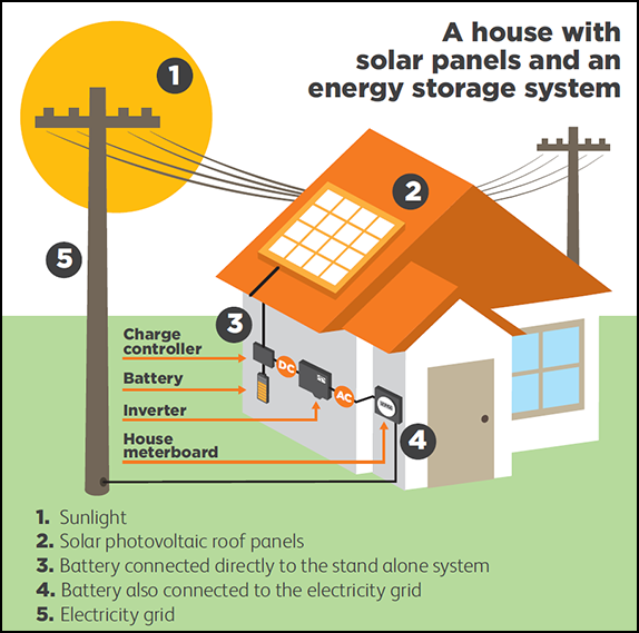
Fig. DS903-F3. Energy storage with batteries. From [4].
According to [4], the main options currently available for household energy storage are lead-acid and lithium-ion batteries. Other less common options include nickel-cadmium, nickel-metal hydride and flow batteries.
A commonly asked question is "Can I go off grid?". Here [4] says "Installing battery storage in your home does not necessarily mean that you can disconnect completely from the electrical grid. Generally speaking, going off grid is not practical for the average urban consumer because (1) it might be difficult to store enough energy to reliably cover your use during cloudy days in winter; (2) you would not be able to sell any surplus energy back to the grid; and (3) there are likely to be significant extra costs (e.g. special additional equipment like the installation of an air-conditioning system) for the battery enclosure".
Nevertheless, the trend is likely to be that battery assemblies ("power-walls"), similar in size to a refrigerator, will be developed to the stage where many households will go off-grid in the future. The Tesla PowerWall 1, intended for exactly this household use, offers a storage capacity of 6.4 kWh, with a continuous power draw of 5 kW [19]. It weighs a little under 100 kg.
It's worth noting that batteries store electricity as DC, while domestic supply is usually AC. Some household devices need the AC transformed to DC. Solar panels produce DC, so the thought arises as to whether households could run entirely on DC.
The answer is slightly complicated, but in summary it would currently appear impractical to run a household entirely on DC. There is a good evaluation of this in Can DC power an entire home? [5].
Energy Storage for Power Stations
Power utilities and power stations may also wish to store energy for later use, particularly if they are using wind turbines, solar arrays, or other non-fuel sources. Because they are operating on a larger scale, other methods of storing energy may be practical for them.
Among these methods, one of the most practical is Pumped Hydro Storage. This involves using excess or available energy to pump water from a lower level up to a higher reservoir. When the energy is required, water is released from the higher level through a turbine, creating electricity as in a hydroelectric station.
Pumped Hydro Storage
Hydroelectric plants make electricity by letting water flow from a higher level to a lower one through a turbine. The flow makes the turbine blades rotate, and the rotation within the turbine causes electricity to be generated in wires around the turbine axle.
In pumped hydro storage, the reverse process happens. Electricity is applied to a turbine, and the blades rotate, making it act like a pump. This pumps water from a lower to a higher level, into a reservoir. When the energy of the stored water is needed, it is allowed to run down through a turbine, just like a normal hydroelectric plant fed from a natural higher source, such as a dam on a mountain river.
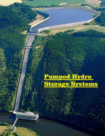
Fig. DS903-F4. [6] Pumped-hydro installation. From [6].
Here is more detail on pumped-hydro, from [6].
"Pumped storage is the most successful, economical and widely used energy-storage technology presently available to electrical utilities for load levelling (peak shaving). It could also be used for storing electrical energy produced from solar and wind energy. Electrical power in excess of immediate demand is used to pump water from a supply (lake, river or reservoir) at a lower level to a reservoir at a higher level. During peak demand period when the demand exceeds the normal generating capacity, water is allowed to flow backwards through a hydraulic turbine, which drives an electric generator and produces power to meet additional demand.
In most pumped storage plants, the turbine generator system is reversible and can serve to pump water as well. In the pumping mode, the generator works as motor and draws electrical power from the electrical network. The turbine then operates as a pump driven by the motor. Start up of the turbine-generator or reversal from motor-pump to turbine-generator requires only a few minutes. The overall energy recovery efficiency of pumped storage, that is, the recovered electrical energy as a percentage of electrical energy used to pump water, is about 70 per cent".
Compressed-Air Energy Storage
Another method of levelling out electricity supplies is to use a temporary excess to drive a compressor to store compressed air. The summary following is from [6].
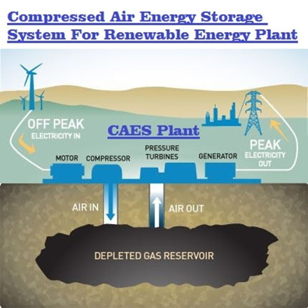
Fig. DS903-F5. A CAES Plant. From [6].
"Electric power in excess of immediate demand is supplied to the motor/ generator unit which drives the compressor. The compressed air, at about 70 atm, is stored in a suitable reservoir. When additional power is needed to meet the demand, the compressed air is released and expanded in a gas turbine connected to the motor/generator unit which now acts as generator. The overall recovery efficiency is 65 to 70 per cent.
Compressed-air storage reservoirs would probably be too large and too expensive for above-the-surface construction; hence underground reservoirs, preferably naturally existing ones, are being considered. Among the possibilities are natural caverns, deep aquifers, depleted gas or oil reservoirs, mined-out rocks or salt caverns, and abandoned mines. A commercial installation is in operation near Bremen, Germany".
Storing Energy as Hydrogen
Another projected method of storing energy is as hydrogen gas under pressure. This would be an attractive method applicable to almost any generating source, and could replace (partly or fully) conventional power station supply and distribution lines with a network of gas lines. Considerable capital investment would be needed, although existing gas pipelines could be incorporated.
The concept is called a HydroWeb. It is described in The HydroSolar package. A diagrammatic representation is given following.
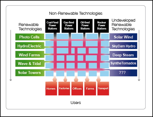
Fig. DS903-F6. The HydroWeb. From [11].
In the diagram, various sources of energy are shown. Most of these produce electricity from generators fed by burning fuels, or from natural motions of water or wind causing generators to rotate. Some, such as photocells (solar panels), produce electricity directly.
In the HydroWeb scheme, all such energy is turned unto hydrogen at the point of production by such means as electrolyzing water into hydrogen and oxygen (the latter is a by-product). In addition, newer developments produce hydrogen directly, from sunlight, in so-called "artificial leaves" which mimic photosynthesis using new catalysts.
At the user end of the HydroWeb, hydrogen is turned back into electricity. The most efficient method is the use of "Fuel Cells", which convert hydrogen directly into electricity in battery-like cells without moving parts, and can be of sizes from small enough to fit into a mobile phone, to large enough to run a complete factory.
Existing generating equipment may also be used, such as gas-turbine generators, or using the hydrogen as the fuel for internal-combustion engine generators.
It might seem inefficient to convert the electricity from, say, wind turbines into hydrogen, and then use the hydrogen at a later stage to make electricity. But the advantages of a national, and possibly international, HydroWeb would be huge. Hydrogen is a material -- taking it from one place and supplying to another distant place, days or months later, would need no voltage conversions and involve negligible transmission losses.
With huge inherent storage, supply of energy from the HydroWeb would be virtually uninterruptible. Users could draw from it from more than one access point, to continue operating even if some pipelines were blocked. And the HydroWeb could even be made self-pressurizing at the points of production, so it would function without compressors or moving parts other than valves.
Battery Energy Storage at Power Stations
Power utilities can use huge banks of batteries as stand-bys to stabilize their consumer grids. What is claimed to be the "world's largest battery", a massive 13,760-cell, 40-megawatt NiCad installation has been set up in Fairbanks, Alaska [12]. It can power the grid for 15 minutes while backup generators start up in the event of an outage.
There are many other types of batteries, including the lithium batteries typically used in electric and hybrid cars. They typically offer better capacity and recharge/discharge rates, but are also usually much more expensive than their more conventional counterparts [12].
However, batteries are a relatively expensive form of storage: $1,400 to $4,900 per kilowatt at commercial scale, depending on the power, capacity, and type of battery.
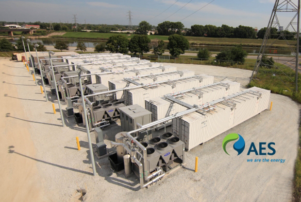
Fig. DS903-F7. AES Energy Storage's Tait battery array in Moraine, Ohio. From [14].
AES Energy Storage, the largest operator of battery-based energy storage resources in North America, recently installed a 40-MW storage array on the PJM Interconnection in Ohio to provide fast-response frequency regulation and grid stabilization services.
Storing Energy as Heat
Energy can also be stored on a large scale as heat. The heat can be stored in molten salt, rock masses, or anything with good heat capacity in a form easily handled.
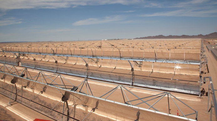
Fig. DS903-F8. The trough-shaped mirrors of the Solana project in Arizona. From [13].
In a new solar project called Solana, energy is gathered in a three-square-mile patch of desert bulldozed flat near Gila Bend, about 50 miles southwest of Phoenix [13]. A sprawling network of parabolic mirrors focuses the sun's energy on black-painted pipes, which carry the heat to huge tanks of molten salt. When the sun has set, the plant can draw heat back out of the molten salt to continue making steam and electricity.
Other energy storage methods exist with possible future potential for use by a power utility. These include solid-state electronic devices, such as Supercapacitors (a development of the capacitors used in many types of circuitry), and Flow Batteries, which combine aspects of conventional batteries and fuel cells [10].
Summary of Energy Storage Techniques
The chart following summarizes most classes of energy storage. The vertical axis shows Specific Energy in Wh/kg (Watt-hours per kilogram, essentially the amount of energy which can be stored in a given mass). The horizontal axis shows Specific Power in W/kg (Watts per kilogram).
Fig. DS903-F9. Energy Storage Chart. From [10].
Most of the items on the chart have already been mentioned, the exception being Flywheels. Flywheels are the base topic of this article -- they are seen here as the most promising and practical technique for household energy storage, and a new technique is described below which could greatly increase their utility. This could move Flywheels up to the top right corner of the chart.
Storing Rotational Energy in Flywheels
Flywheels are an ancient method of storing energy, with perhaps their oldest use in the early potter's wheel, where the potter spins a circular table on which a pot is to be thrown. Electric potters wheels are still used today, and earlier industrial uses had them driven by belts connected to steam engines, but the earliest models seem to have spun by a treadle powered by the potter's feet.
By storing energy in a heavy rotating wheel, the potter is able to achieve a regular circular motion -- thrown clay pots are based on shapes with circular cross-sections, varied in diameter by the separation of the potter's two hands.

Fig. DS903-F10. Throwing a Clay Pot on a Potter's Wheel. From [17].
According to Wikipedia [18], a stone potter's wheel found at the Mesopotamian city of Ur in modern-day Iraq has been dated to about 3129 BC, but fragments of wheel-thrown pottery of an even earlier date have been recovered in the same area. However, southeastern Europe and China have also been claimed as possible places of origin.
There is a good explanations of Flywheel Energy Storage Systems (FESS) in [8]. Below are some extracts from there. Essentially, a FESS is just an electric motor/generator -- electrical energy can be fed in, increasing its rate of rotation, or drawn out, causing the rotor to slow.
"Flywheel energy storage systems (FESS) use electric energy input which is stored in the form of kinetic energy. Kinetic energy can be described as 'energy of motion', in this case the motion of a spinning mass, called a rotor. The rotor spins in a nearly frictionless enclosure.
When short-term backup power is required because utility power fluctuates or is lost, the inertia allows the rotor to continue spinning and the resulting kinetic energy is converted to electricity. Most modern high-speed flywheel energy storage systems consist of a massive rotating cylinder (a rim attached to a shaft) that is supported on a stator by magnetically levitated bearings. To maintain efficiency, the flywheel system is operated in a vacuum to reduce drag.
The flywheel is connected to a motor-generator that interacts with the utility grid through advanced power electronics. Some of the key advantages of flywheel energy storage are low maintenance, long life, and negligible environmental impact.
Flywheels can bridge the gap between short-term ride-through power and long-term energy storage with excellent cyclic and load following characteristics. Typically, users of high-speed flywheels must choose between two types of rims: solid steel or carbon composite. The choice of rim material will determine the system cost, weight, size, and performance. Composite rims are both lighter and stronger than steel, which means that they can achieve much higher rotational speeds".
Fig. DS903-F11. Flywheel stores Energy. From [10].
Construction of Flywheels
The amount of energy that can be stored in a flywheel is a function of the square of the rpm (Revolutions Per Minute), making higher rotational speeds desirable. Currently, high-power flywheels are used in many aerospace and UPS (uninterruptible power supply) applications and in telecommunications applications. For utility-scale storage a "flywheel farm" approach can be used to store megawatts of electricity for applications needing minutes of discharge duration.
The amount of energy that can be stored is proportional to the object's moment of inertia times the square of its angular velocity [8]. To optimize the energy-to-mass ratio, the flywheel must spin at the maximum possible speed. Rapidly rotating objects are subject to significant centrifugal forces, so while dense materials can store more energy, they are also subject to higher centrifugal force and thus may be more prone to failure at lower rotational speeds than low-density materials.
Therefore, tensile strength is more important than the density of the material. Low-speed flywheels are built with steel and rotate at rates up to 10,000 rpm. More advanced FESS achieve attractive energy density, high efficiency and low standby losses (over periods of many minutes to several hours) by employing four key features: 1) rotating mass made of fibre-glass resins or polymer materials with a high strength-to-weight ratio; 2) a mass that operates in a vacuum to minimize aerodynamic drag; 3) mass that rotates at high frequency; and 4) air or magnetic suppression bearing technology to accommodate high rotational speed.
Advanced FES systems have rotors made of high strength carbon-fibre composites, suspended by magnetic bearings, and spinning at speeds from 20,000 to over 50,000 rpm in a vacuum enclosure [7]. Such flywheels can come up to speed in a matter of minutes --reaching their energy capacity much more quickly than some other forms of storage.
These FESS operate at a rotational frequency in excess of 100,000 rpm, with tip speeds in excess of 1000 m/s. FESS are best used for high power, low energy applications that require many cycles.
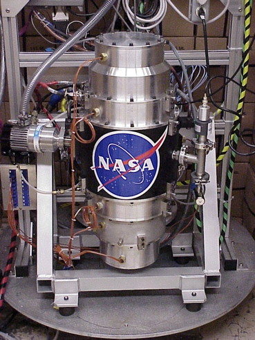
Fig. DS903-F12. NASA G2 Flywheel. From [7].
In summary, flywheel systems have several advantages over chemical energy storage. They have high energy density and substantial durability, which allows them to be cycled frequently with no impact to performance. They also have very fast response and ramp rates. In fact, they can go from full discharge to full charge within a few seconds or less. They are especially attractive for applications requiring frequent cycling, given that they incur limited life reduction if used extensively (i.e., they can undergo many partial and full charge-discharge cycles with trivial wear per cycle.)
Flywheels in moving vehicles
Flywheels can be used in moving vehicles. This may be as a "smoothing" energy store, holding excess energy from a motor for use at peak demand, or recovered energy from braking. Public-transport vehicles making regular stops, such as suburban buses or trains, can run between stops on their flywheel energy alone, topping up the flywheel speed during their stops.
Buses. The concept of a flywheel-powered bus was developed and brought to fruition during the 1940s by Oerlikon (of Switzerland), with the intention of creating an alternative to battery-electric buses for quieter, lower-frequency routes, where full overhead-wire electrification could not be justified [22].

Fig. DS903-F13. Loading up a Gyrobus flywheel. From [22].
Rather than carrying an internal combustion engine or batteries, or connecting to overhead powerlines, the gyrobus carried a large flywheel that was spun at up to 3,000 rpm by a "squirrel cage" motor [22]. Power for charging the flywheel was sourced by means of three booms mounted on the vehicle's roof, which contacted charging points located at passenger stops or terminals.
To obtain tractive power, capacitors would excite the flywheel's charging motor so that it became a generator, in this way transforming the energy stored in the flywheel back into electricity. Vehicle braking was electric, and some of the energy was recycled back into the flywheel, thereby extending its range.
Fully charged, a gyrobus could typically travel as far as 6 km on a level route at speeds of up to 50 to 60 km/h. The installation in Yverdon-les-Bains (Switzerland) sometimes saw vehicles needing to travel as far as 10 km on one charge. Charging a flywheel took between 30 seconds and 3 minute.
Different types of gyrobus have been in use over the years in many countries, including the Belgian Congo. While functionally successful, their higher costs compared to diesel have led to them being superseded on economic grounds.
In July 2014, GKN acquired Williams Hybrid Power and intends to supply 500 carbon-fibre Gyrodrive electric flywheel systems, originally designed for Formula one motor racing, to urban bus operators over the next two years. In September 2014, Oxford Bus Company announced that it is introducing 14 Gyrodrive hybrid buses on its Brookes Bus operation.
Cars. Flywheels have also been used in cars, usually as supplementary energy sources for use when surges of power are needed. An example was the Chrysler Patriot Flywheel/Turbine hybrid [15].
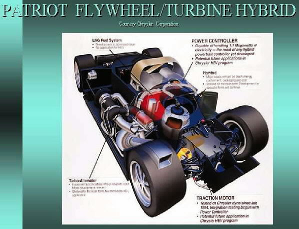
Fig. DS903-F14. Patriot Flywheel/Turbine Hybrid. From [15].
During the 1990s, Rosen Motors developed a gas turbine powered series hybrid automotive powertrain using a 55,000 rpm flywheel to provide bursts of acceleration which the small gas turbine engine could not provide [7]. The flywheel also stored energy through regenerative braking.
The flywheel was composed of a titanium hub with a carbon-fibre cylinder and was gimbal-mounted to minimize adverse gyroscopic effects on vehicle handling. The prototype vehicle was successfully road tested in 1997, but was never mass-produced.
Fig. DS903-F15. The Rosen Flywheel System. From [15].
In 2013, Volvo announced a flywheel system fitted to the rear axle of its S60 sedan. Braking action spins the flywheel at up to 60,000 rpm and stops the front-mounted engine. The 20-centimetre, 6-kilogram carbon-fibre flywheel spins in a vacuum to eliminate friction.
When partnered with a four-cylinder engine, it offers up to a 25 percent reduction in fuel consumption versus a comparably performing turbo six-cylinder, providing an 80 hp boost and allowing it to reach 100 kilometres per hour in 5.5 seconds.
Rail vehicles. Flywheel systems have been used experimentally in small electric locomotives for shunting or switching [7]. Larger electric locomotives have sometimes been fitted with flywheel boosters to carry them over gaps in the third rail. Advanced flywheels, such as the 133 kWh pack of the University of Texas at Austin, can take a train from a standing start up to cruising speed.
The Parry People Mover is a railcar which is powered by a flywheel [7]. It was trialled for 12 months on the Stourbridge Town Branch Line in the West Midlands, England during 2006 and 2007 It was intended to be introduced as a full service by the train operator (London Midland) in December 2008, once two units had been ordered. In January 2010, both units were in operation.
The Gyroscope Effect with Flywheels
When used in vehicles, flywheels also act as gyroscopes, since their angular momentum is typically of a similar order of magnitude as the forces acting on the moving vehicle [7]. This property may be affect a vehicle's handling characteristics while turning or driving on rough ground -- driving onto the side of a sloped embankment may cause wheels to partially lift off the ground, as the flywheel opposes sideways tilting forces.
The resistance of angular tilting can be almost completely removed by mounting the flywheel within an appropriately applied set of gimbals, allowing the flywheel to retain its original orientation without affecting the vehicle.
Flywheels as household energy stores
The KPW (Kilogram Power Wheel)
All the technology is already present to develop small flywheel devices as household power stores, playing the same role as battery assemblies like Tesla's PowerWall. These flywheels should be much less massive than a comparable battery bank, and should be cheaper to make and easier to maintain. They should also have additional advantages in not needing rarer source materials such as lithium.
In this article, such a device is called a KPW (Kilogram Power Wheel). The target for implementation is a device about as big as a record player, with a rotor weighing about a kilogram. This is contrasted with the Tesla PW, which is the size of a refrigerator and weighs close to 100 kg.
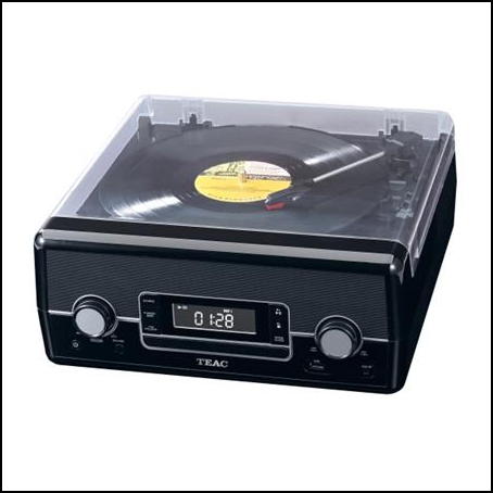
Fig. DS903-F16. The KPW would be of similar size to a record player. From [23].
The KPW would be made up of a flywheel and the electromagnetic windings needed for it to act as a generator or motor, with the flywheel magnetically levitated (magnetic bearings) and enclosed in an evacuated capsule. This is a standard design which is virtually friction-less -- once in motion, the flywheel should continue to rotate indefinitely at the same speed until power is added or withdrawn.
Compared with most flywheels, the KPW would be on the smaller size. The energy held by a flywheel at any given time depends directly on its mass, and on the square of its speed of rotation.
We need to be able to calculate the energy held in various configurations of flywheel. A useful too here is a Web facility which uses Javascript to calculate output energy from a flywheel's mass, diameter, rate of spin in rpm (revolutions per minute) [20]. The reader can use this Flywheel Energy Calculator to make such calculations -- a snapshot of one such calculation follows.
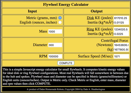
Fig. DS903-F17. Energy stored in a 1 kg flywheel. From [20].
This base example is for a flywheel of mass 1 kg (1000 grams) and diameter 300 mm (similar to a LP record), and a spin rate of 100,000 rpm. Output is given in joules for two flywheel formats, a disc (about 617,000 joules) and a ring (about 1,234,000 joules).
These figures are for ideal disc or ring formats. The disc format is like that of an LP record, with a uniform thickness and density from centre to rim. The ring format is like that for a bicycle wheel, assumed to have all of its mass at its rim and tyre, and assumed negligible mass for its spokes and axle. Real flywheels lie between these two formats.
Here we will use kiloWatt-hours (kWh) as our comparison unit of energy. On your electricity bill, 1 kWh is usually called "1 unit". The average Australian house uses 18 kWh per day, and 6,570 kWh per year [25]. It was noted above that the Tesla PowerWall 1 offers a storage capacity of 6.4 kWh.
Another Web facility at [21] does conversion of Joules to kWh. You can do this yourself by dividing a figure in Joules by 3,600,000 (3.6 million).
So the 1 kg, 300 mm, base flywheel example above, with a spin rate of 100,000 rpm, has an energy storage of about 0.34 kWh for the ring format, and 0.17 kWh for the disc format. We would need to increase this energy storage by a factor of 3 to 20 for a useful device.
Increasing the flywheel mass by 10 times, to 10 kg, would give 10 times the output, about 3.3 or 1.65 kWh. A bank of 10 of the base units would have the same total result. This would need an engineering reconfiguration to accommodate the heavier flywheel.
Doubling the diameter of the flywheel, to 600 mm, would give four times the output. For the base example, the outputs would be 1.37 kWh (disc) and 0.68 kWh. This would involve a major re-design of the device, taking it out of the "record-player" heft.
Increasing the rotation speed of the flywheel is the easiest way to raise its energy storage. At a rate of 200,000 rpm, with the disc configuration, the storage would be 0.68 kWh -- without any change to the engineering. At 432,100 rpm, the ring-configuration flywheel would have a capacity of 6.4 kWh -- the same as the Tesla Powerwall.
So increasing the flywheel rotation rate is the obvious way to go. No re-configuration is needed, just feed in more power. The limitation is in the strength of the rotor -- with high enough centrifugal forces, the rotor will disintegrate.
Here then is the main development route to get commercial KPWs available for supply and fitting in domestic usage. Currently, carbon-fibre rotors are out-performing metal ones as far as maintaining integrity under high rotation rates is concerned. Fused-silica rotors appear to have promise here.
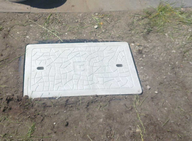
Fig. DS903-F18. Cover to a communications service pit. From [26].
Because of the rotor-disintegration possibility, household KPWs would normally be mounted in small service pits, as commonly used now for communications and utilities. It would be good practice to have two KPWs in separate pits at any site -- this would be convenient anyway, for maintenance and redundancy.
Two pits would also be more convenient for an external power top-up -- the contractor would bring in a buggy with its own large flywheel store, and transfer energy to each of the home flywheels in turn. This should be a rapid procedure, taking only a few minutes, unlike re-charging from mains power.
The KPT (Kilogram Power Torus)
The KPW storage device as described can be manufactured with today's technology. An improved device, the KPT or Kilogram Power Torus, is possible by applying a little R&D input to modify the KPW.
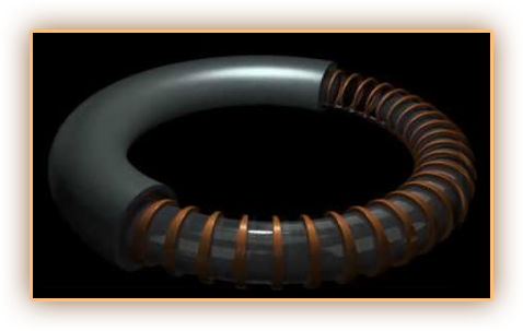
Fig. DS903-F19. Carbon-Fibre Torus vessel with encased electro magnet windings. From [24].
In this modification, the KPW rotor is replaced by a torus, kept suspended by a magnetically levitating harness. The motor/generator windings are within or around the torus, so there is no axle in the device.
In theory, a KPT rotor should be less prone to breakage under high centrifugal forces, as it floats within a harness rather than forming a solid connection with an axle. Using high-strength magnets, it should be possible to control the torus within the harness at much higher rotation speeds, and so to achieve much higher energy storage rates.
The illustration is from a description of an experimental aircraft propulsion system [24], "Basic Design of the Dual Mercury Torus Propulsion System". This notes that it contains a "Carbon-Fibre Torus Structure with Gold wire windings placed Integral to the structure. Each band of windings is a separate electro-magnet that can be turned on and off by a computer program, allowing acceleration to tremendous speeds".
* * * * * * * * * * * * * * * * * *

References and Links
[1]. The National Grid Network. http://fiziknota.blogspot.com.au/2009/04/national-grid-network.html.
[2]. The Smart Grid: How automation empowers the future of Electricity. https://blog.phoenixcontact.com/marketing-sea/2017/04/smart-grids-how-automation-empowers-the-future-of-electricity/ .
[3]. The TIG Welder -- AC or DC?. https://cadcaminfo.wordpress.com/prototyping/the-tig-welder-ac-or-dc/ .
[4]. Battery storage safety: frequently asked questions (FAQ). https://www.solaraccreditation.com.au/consumers/solar-battery-storage-faqs.html .
[5]. Chris Gammell. Can DC power an entire home?. http://chrisgammell.com/can-dc-power-an-entire-home/ .
[6]. Mechanical Energy Storage Systems. http://techatmech.blogspot.com.au/2015/06/mechanical-energy-storage-systems.html .
[7]. Flywheel energy storage. https://en.wikipedia.org/wiki/Flywheel_energy_storage .
[8]. Flywheels. http://energystorage.org/energy-storage/technologies/flywheels .
[9]. Let's Explore Flywheel Energy Storage Devices. http://wiredcosmos.com/2013/02/27/lets-explore-flywheel-energy-storage-devices/ .
[10]. Y T Qiu. Energy Storage: Why is Energy Storage Important?. http://zebu.uoregon.edu/disted/ph162/l8.html .
[11]. David Noel. The HydroSolar package: The complete answer to concerns about energy shortages, oil crises, greenhouse gases, global warming, power station pollution, and environmental headaches?. http://www.aoi.com.au/bcw/HydroSolar.htm .
[12]. Chris Nelder. Saving the sun's shine: Storage technology could revolutionize the power grid. https://qz.com/29069/saving-the-suns-shine-storage-technology-could-revolutionize-the-power-grid/ .
[13]. Matthew L Wald. Arizona Utility Tries Storing Solar Energy for Use in the Dark. http://www.nytimes.com/2013/10/18/business/energy-environment/arizona-utility-tries-storing-solar-energy-for-use-in-the-dark.html?_r=0&pagewanted=all .
[14]. U.S. grid power storage charges up. http://www.getreallist.com/u-s-grid-power-storage-charges-up.html .
[15]. Brian Eiland. Flywheel Energy Storage Systems. https://www.boatdesign.net/threads/flywheel-energy-storage-systems.32427/ .
[16]. Pentadyne Seeks Funding for Using Flywheels in Railway System to Save Power. https://www.greenoptimistic.com/mechanical-battery-flywheel/ .
[17]. Pottery Wheel Throwing. http://www.wise-adventures.ca/-new--potter-s-wheel.html .
[18]. Potter's wheel. https://en.wikipedia.org/wiki/Potter%27s_wheel .
[19]. Tesla Powerwall. https://en.wikipedia.org/wiki/Tesla_Powerwall .
[20]. Flywheel Energy Calculator. http://www.botlanta.org/converters/dale-calc/flywheel.html .
[21]. Joules to kWh conversion. http://www.rapidtables.com/convert/energy/Joule_to_kWh.htm .
[22]. Gyrobus. https://en.wikipedia.org/wiki/Gyrobus .
[23]. Turntables. https://www.jbhifi.com.au/headphones-dj/turntables/ .
[24]. TR3 Black Manta "A51". http://tr3blackmanta.com/ .
[25]. How Much Power is Needed to Run an Average Home?. https://https://www.platinumelectricians.com.au/blog/power-needed-run-average-home/ .
[26]. Dig Dug Mini Digging. http://www.digdug.com.au/prepro_leadin.html .
Go to the Devices Home Page
Version 1.0 compilation started 2017 Oct 7, on Web 2017 Oct 29.
